Initialization of pcKM1024i(CB)
Enter the IP address and channel number of the printing controller
and click "INIT" to initialize the connection.
Automatically detects the driver type, and displays it in the
detected device type field.
After successful initialization, waveform settings can be
configured.
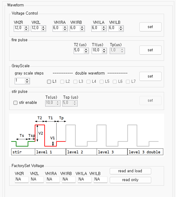
Waveform generals
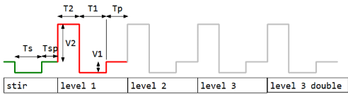
- The stir waveform is disabled by default and can be enabled if required.
- In binary printing, only the level 1 waveform is output.
- In grayscale printing, waveforms are output up to the specified grayscale level.
Voltage setting

Sets the voltage of each VH1 and VH2 channel in 0.1 V
increments.
Condition: 5.0 < VH1 < VH2 < 21.0

Press the "Read" button to read the contents of the
EEPROM inside the KM1024i printhead and display the
factory-optimized values.
The "Read and Load" button reads the values and
automatically loads them into the
VoltageControl settings above.
Pulse setting

T2 is the duration of the VH2 voltage, and
T1 is the duration of the VH1 voltage.
Tp is meaningful only when the grayscale level is
greater than or equal to 2.
In a multi-drop waveform, it represents the time interval between
the end of the VH1 voltage and the start of the next VH2 voltage.
Stirring

The jetting waveform is affected by the nozzle on/off pattern, while
the stir waveform is applied to all nozzles.
The stir waveform is disabled by default and can be enabled when
required.
The voltage consists only of VH1, which is
maintained for Ts duration, followed by
0 V for Tsp duration.
Greyscale

The gray scale steps value ranges from
1 to 7, where
1 corresponds to binary printing.
One additional waveform is added for each grayscale level.
If the waveform count should increase by +2 instead
of +1 at a specific level, enable the
"Double Waveform" option.
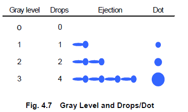
For example, if the settings are configured as shown above:
gray scale steps = 3
Double Waveform L3 = checked