Encoder and LED strobo
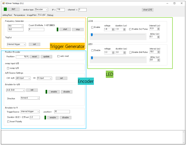
Trigger Generator
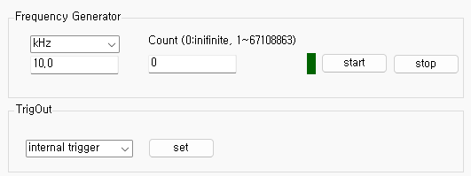
The generated internal trigger signal is used as follows:
- External trigger signal distributed to all controllers on the bus
- Reference trigger signal for LED strobe control
- Reference signal for the encoder emulator
- Trigger-out signal output through the BNC connector
Both the trigger frequency and trigger count (including infinite mode) can be configured.
Encoder processor
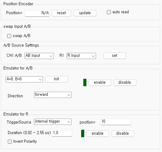
- By default, externally input encoder signals are used.
- The encoder signal (external or emulated) is distributed to all controllers on the bus.
- The encoder counter value can be read or reset through the Position Encoder interface.
- The A/B encoder channels can be swapped in software to reverse the detected moving direction.
- An internal encoder emulator is provided, allowing the generated signal to be used as an A/B encoder signal.
-
To connect the emulator output to the A/B encoder signal, select
the Emulator output in the
A/B Source Setting and enable the emulator.
Afterward, when the internal trigger is generated, the A/B emulation signal is produced and distributed over the bus.
LED strobo light control
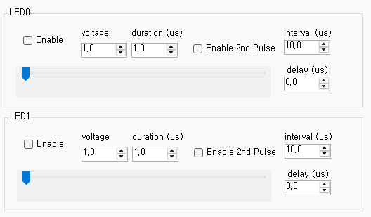
- The LED strobe operates synchronously with the internal trigger signal.
- Voltage, delay, and duration values can be adjusted for every two channels.
- Enable the output by checking the Enable checkbox.
- A second strobe pulse can be enabled by checking the "Enable 2nd Pulse" option and adjusting the interval value.
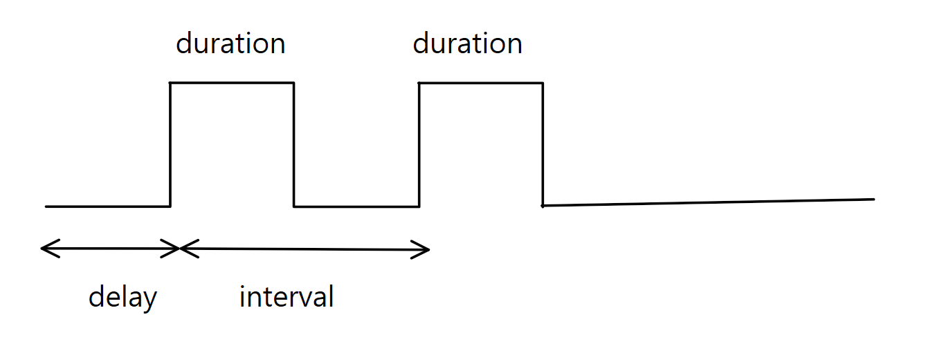
In the software interface, the interval value is
used.
However, in the library interface, the parameters are represented as
delay and delay2.
The relationship is:
delay2 = delay + interval.